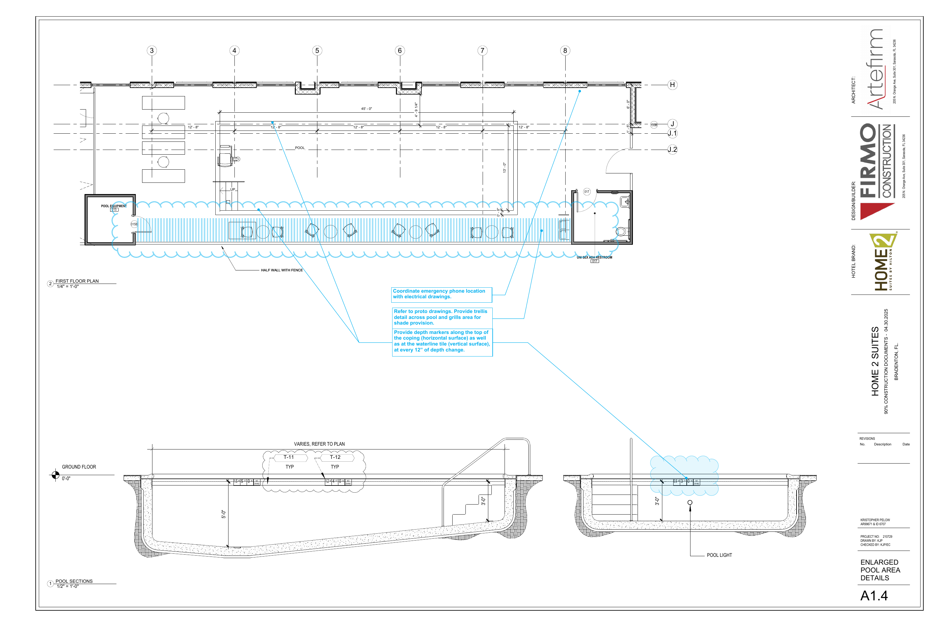
A1.4 · Enlarged pool area details Home2 Suites · Bradenton
TAKEOFF / COUNTS
Select an item to isolate its marks.
CONCRETE / AREAS / LENGTHS
Plan scale checked: 45′ and 12′-8″ dimensions.
Select a quantity to show its measured boundary and basis.
Concrete thickness / quantity basis
Patio and room slabs: 4″ assumed. Pool floor: 8″ assumed. Pool walls: 8″ per plan, with 6″ assumed freeboard. Steps use a solid-fill basis with four approximately 12″ treads, 9″ risers and 2′-9″ width.
Pool floor 14.5 CY + walls 13.2 CY + steps 0.8 CY = 28.4 CY. Patio 14.5 CY + equipment slab 0.7 CY + restroom slab 0.9 CY. Combined quantity: 44.6 CY before waste, footings and unshown thickened edges. Totals use unrounded values.
Confirm shell, deck, room-floor and step construction against their details.
ASSEMBLIES / MATERIALS
01 · Pool shell / finish
Plan prints 45′-0″ × 13′-0″. Sections show 3′-0″ shallow depth and 5′-0″ deep depth, with sloping floor and entry steps. Obtain shell reinforcement, waterproofing and finish specifications from the pool design.
02 · Pool lift / accessible entry
One lift and one stair-entry assembly shown. Coordinate lift foundation, deck clearances, operating range and access provisions with A0.3 and the pool equipment submittal.
03 · Deck / coping / waterline tile
Coordinate deck finish, drainage and coping. T-11 and T-12 are shown as typical finish tags in section; link them to the finish schedule and pool specifications.
04 · Depth / no-diving markers
Hilton note requires markers on top of coping and at vertical waterline tile, at every 12″ of depth change. Sections illustrate 3′, 4′ and 5′ markers with metric equivalents and NO DIVING text. Set final quantities and spacing from the pool layout.
05 · Half wall / fence
South edge is labeled half wall with fence. Coordinate height, infill, supports, gates and connections with pool-barrier details and site plan.
06 · Trellis / shade
Hilton annotation requires a trellis detail across the pool and grills area; refer to prototype drawings. Coordinate structure, supports, finish and footprint.
07 · Emergency phone
Coordinate emergency-phone location with electrical drawings. Carry device, mounting, power/communications and signage into the equipment layout.
08 · Pool lighting / equipment
A pool light is called out in section. Pool Equipment Room 015 is identified in plan. Coordinate full light count, pool equipment, piping, controls and electrical connections with pool/MEP drawings.
09 · Restroom / exterior fixtures
Restroom 017 shows a water closet and lavatory with accessory outlines. Link accessible clearances, grab bars, accessories and finishes to enlarged restroom details. Identify the two exterior basin-shaped fixtures through plumbing.
10 · Furniture / door assemblies
Four loungers, eight deck chairs and six round tables shown. Match outdoor furniture to FF&E. Coordinate the three tagged doors with door/hardware schedules and pool-access requirements.
PLAN NOTES
1. Coordinate emergency phone location with electrical drawings.
2. Refer to prototype drawings and provide a trellis detail across pool and grills area for shade.
3. Provide depth markers along top of coping and at waterline tile at every 12″ of depth change.
SHEET REFERENCE REGISTER
All printed dimensions / finish references
45′-0″ × 13′-0″ pool; 12′-8″ grid spacing; 4′-9¼″ north offset; 6′-0″ east return; 1′-5″ offset; 0′-8″ pool wall; 3′-0″ shallow / 5′-0″ deep; ground floor 0′-0″. Finish tags T-11 and T-12, both typical.
Depth examples: 1.5 m / 5 ft, 1.2 m / 4 ft and 0.9 m / 3 ft, each with NO DIVING text. Grids 3–8, H, J, J.1 and J.2. Related drawings: electrical, prototype trellis, pool design, accessible-entry and finish schedules.
SOURCE
A1.4 · PDF page 12
36″ × 24″ sheet
Select an assembly to highlight its source.
PRINTED DIMENSIONS
BROKEN CHAINS & PLAN ISSUES
BC-01 · Coordination
Trellis/shade provision is requested by the Hilton annotation; link the prototype and structural details, locations and supports.
BC-02 · Coordination
Emergency-phone location is referred to electrical. Confirm device type, location, mounting and power/communications.
BC-03 · Coordination
Depth-marker annotation requires both horizontal and vertical markers at every 12″ of depth change. Link the marker layout and full quantities; three section examples are not the full installation count.
BC-04 · Coordination
T-11 and T-12 finish tags need the applicable finish schedule, pool tile and coping specifications.
BC-05 · Coordination
The pool-light symbol is shown only in section on A1.4. Obtain the full lighting layout and reconcile it with pool equipment and electrical drawings.
BC-06 · Coordination
Half wall with fence is labeled without a complete barrier/gate detail here. Link fence height, infill, supports and gate hardware to the pool/site details.
PI-01 · Coordination
Two basin-shaped fixtures outside Restroom 017 are unlabeled. Confirm their fixture type, mounting, accessibility and plumbing connections.
BC-07 · Coordination
Coordinate the lift and stair entry with A0.3 pool-access requirements; link lift mounting, clear deck space and handrail details.
PI-02 · Coordination
Concrete volumes use explicit thickness/freeboard and solid-step assumptions. Confirm shell-floor thickness, reinforcement, patio/room slab thicknesses, footings and step construction before final concrete procurement.
BC-08 · Coordination
Measured south half wall and fence are 66.8 LF each. Heights, wall thickness, footings, material and gate requirements need the barrier detail; west boundary is recorded separately at 16.3 LF.
BC-09 · Coordination
Depth/signage register carries six sets as a 3-depth × 2-surface basis. Confirm repeats, placement and sign specification against the full pool layout; do not treat this basis as a complete installed signage count.
Add working issue
Working notes · This session