A1.3 · Architectural site details Home2 Suites · Bradenton
TAKEOFF / COUNTS
Select an item to isolate its marks.
ASSEMBLIES / MATERIALS
01 · Curb-ramp assemblies
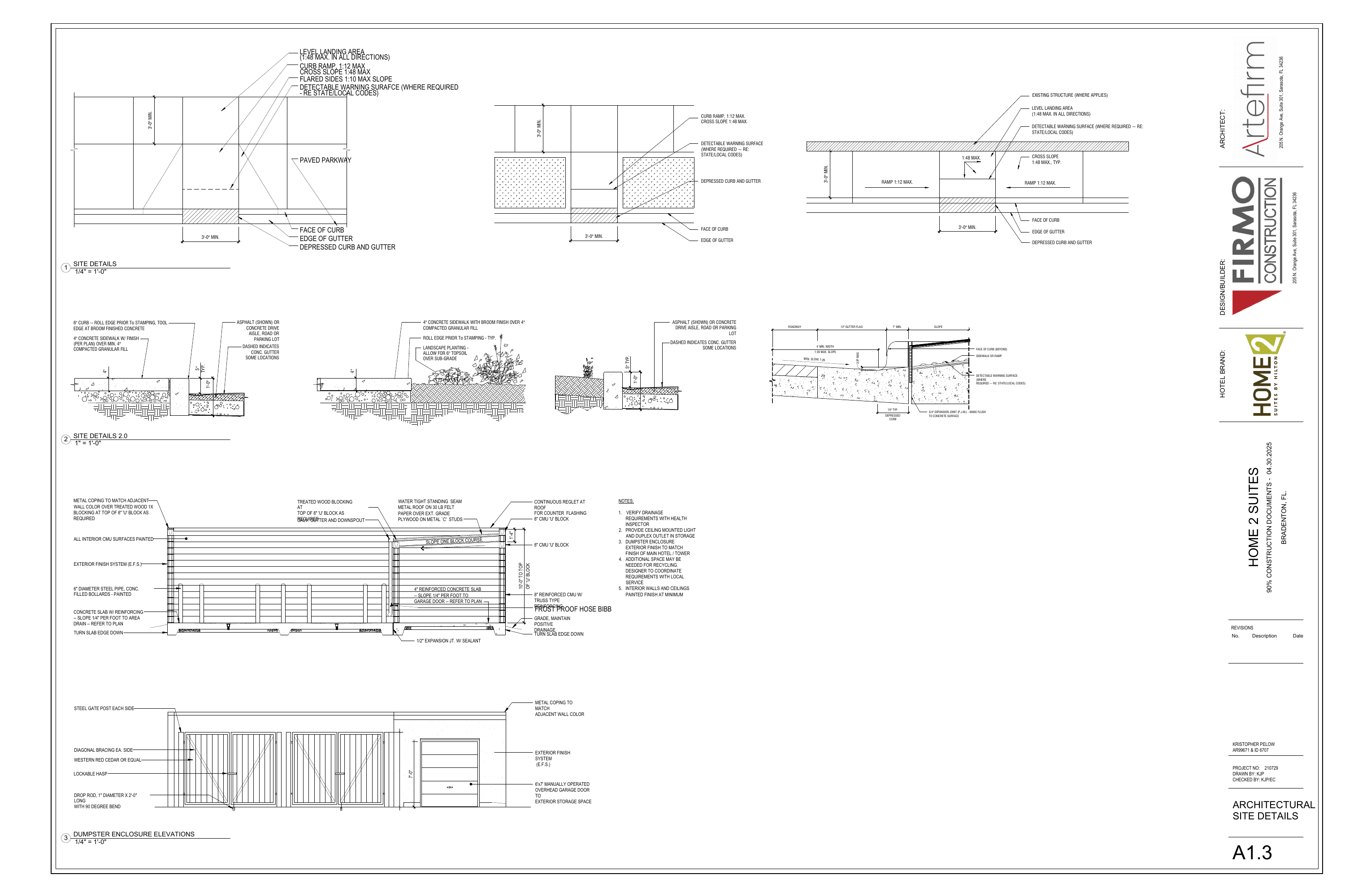
Three illustrated arrangements: flared ramp at paved parkway, ramp between planted areas, and parallel ramps at an existing structure. Ramp slope 1:12 maximum; cross slope and level landing 1:48 maximum. Flared sides 1:10 maximum. Printed ramp/landing widths are 3′-0″ minimum. Detectable warning surfaces where required by the sheet note.
02 · Sidewalk / curb assembly
4″ concrete sidewalk over minimum 4″ compacted granular fill. Broom finish or finish per plan; 6″ curb. Roll edge before stamping and tool edge at broom-finished concrete. Asphalt or concrete drive aisle/road/parking adjoins.
03 · Landscape edge assembly
4″ broom-finished concrete sidewalk over 4″ compacted granular fill. Allow 6″ topsoil over landscape subgrade; roll exposed edge before stamping.
04 · Depressed curb / gutter assembly
Depressed curb and gutter with detectable warning surface where required. Section labels a 12″ gutter flag, 4′ minimum width with 1:20 maximum slope, 3/8″ maximum transition, and 3/4″ expansion joint made flush with concrete.
05 · Enclosure CMU / coping
8″ reinforced CMU with truss-type reinforcing and 8″ CMU U-block. Top of U-block shown at 10′-0″. Treated wood blocking and metal coping to match adjacent wall color. Exterior finish system; interior CMU painted.
06 · Storage roof assembly
Watertight standing-seam metal roof over 30 lb felt, exterior-grade plywood and metal C-studs. Slope one block course. Continuous reglet/counterflashing, galvanized gutter and downspout.
07 · Concrete slabs / drainage
Reinforced enclosure slab slopes 1/4″ per foot to area drain; two drain symbols are drawn. Storage slab is 4″ reinforced concrete, sloped 1/4″ per foot toward garage door. Turn down slab edges; 1/2″ expansion joint with sealant.
08 · Bollard assembly · 7 shown
6″ diameter steel pipe, concrete filled and painted. Seven pipe profiles appear in the enclosure elevation.
09 · Gate assemblies · 2 double sets
Four gate leaves with western red cedar or equal and diagonal bracing. Steel post at each side of each set: four posts shown. Two lockable hasps and two drop rods shown. Drop rod: 1″ diameter × 2′-0″ long with 90° bend.
10 · Overhead door assembly · 1
6′ × 7′ manually operated overhead garage door to exterior storage. Coordinate track, support and opening details.
11 · Hose bib · 1 indicated
Frost-proof hose bib callout points to the enclosure/storage dividing wall. Coordinate water supply and mounting.
12 · Storage electrical · note 2
Provide one ceiling-mounted light and one duplex outlet in storage. Their takeoff marks identify note 2; final device positions and circuiting belong on the electrical layout.
PLAN NOTES
1. Verify drainage requirements with the health inspector.
2. Provide ceiling-mounted light and duplex outlet in storage.
3. Dumpster enclosure exterior finish to match main hotel / tower.
4. Additional recycling space may be needed; designer to coordinate requirements with local service.
5. Interior walls and ceilings to have painted finish at minimum.
SOURCE
A1.3 · 04.30.2025 · PDF page 11
36″ × 24″ sheet
Select an assembly to highlight its source.
DETAIL REGISTER
BROKEN CHAINS & PLAN ISSUES
BC-01 · Coordination
Locate each curb-ramp arrangement and the dumpster/storage enclosure on the architectural site and civil plans. Detail component counts apply to the enclosure illustrated here.
BC-02 · Coordination
Enclosure slab notes refer to plan and call for drainage review with the health inspector. Link the two shown area drains to plumbing/civil connections and the selected discharge route.
BC-03 · Coordination
Link the storage ceiling light, duplex outlet and frost-proof hose bib to electrical/plumbing layouts, device locations and connections.
BC-04 · Coordination
Confirm required recycling space with the local service and coordinate dumpster size, collection access and gate openings.
BC-05 · Coordination
Link CMU reinforcement, slab/footing reinforcement, gate-post embedment and roof connections to structural details.
BC-06 · Coordination
Select the detectable warning surface and required locations; coordinate each ramp/landing elevation and gutter transition with civil grading.
PI-01 · Coordination
Gate opening widths, overall enclosure dimensions and bollard embedment are not dimensioned in these elevations. Link the enclosure plan and attachment details before sizing those assemblies.
Add working issue
Working notes · This session