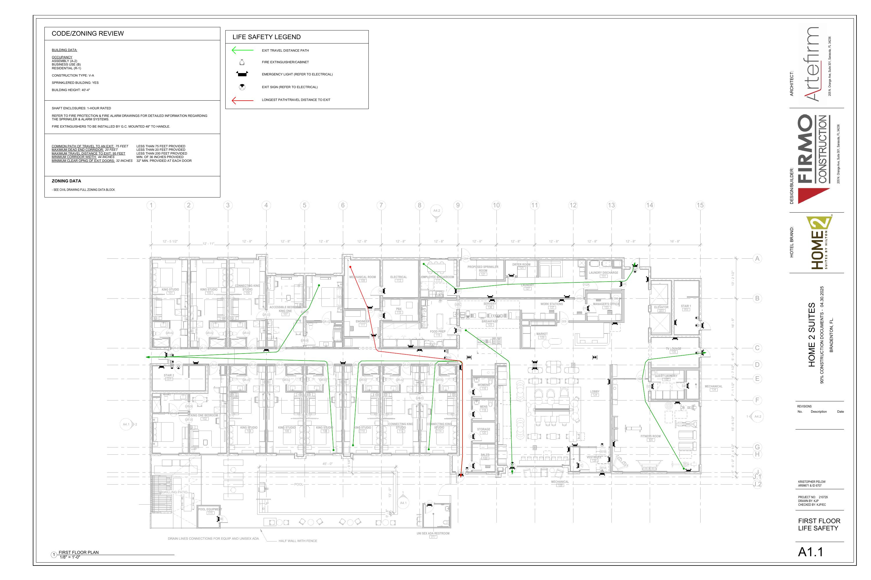
A1.1 · First floor life safety Home2 Suites · Bradenton
SYMBOL TAKEOFF / COUNTS
65 numbered symbols · select a type to isolate its marks.
PLAN NOTES / REQUIREMENTS
01 · Building / occupancy
Assembly A-2, business B and residential R-1. Construction Type V-A; sprinklered building. Printed building height: 40′-4″.
02 · Rated shaft enclosure
1-hour rated shaft enclosures. Coordinate wall construction, openings and penetrations with A0.2 wall assemblies and the shaft details.
03 · Exit travel paths
Green arrows identify exit travel paths; the red route identifies the longest path. Red route starts in Mechanical 109 and runs to the south exterior exit beside Sales 122.
04 · Stairs / vertical circulation
Two labeled stairs: Stair 2 / 001 at the west end and Stair 1 / 002 at the east end. Elevator 003 is adjacent to Stair 1.
05 · Common path / dead ends
Code table: common path to an exit 75′, with less than 75′ provided; dead-end corridor 20′, with less than 20′ provided.
06 · Exit travel distance
Code table prints maximum travel distance to exit 95′, while the provided column says less than 200′. Resolve the conflicting values against the red route.
07 · Corridor / door clearance
Code table prints minimum corridor width 44″, while provided column says minimum 36″. Exit-door clear opening is listed as 32″ minimum, with 32″ minimum provided at each door.
08 · Fire extinguisher / cabinet
Legend identifies fire extinguisher/cabinet. General contractor installs extinguishers with handle at 48″. Coordinate cabinet depth, wall construction and accessible-route projections.
09 · Emergency lighting
Legend identifies emergency lights and refers to electrical drawings. Reconcile architectural locations with E2.0 fixture types, emergency operation and switching.
10 · Exit signs
Legend identifies exit signs and refers to electrical drawings. Coordinate sign direction and visibility with the actual exit routes and electrical fixture schedule.
11 · Sprinkler / fire alarm
Building is sprinklered. A1.1 directs sprinkler and alarm system detail to fire protection and fire alarm drawings. Proposed Sprinkler Room 121 is labeled along the north service area.
12 · Guestroom / accessible route
Guestroom corridor connects the west and east circulation areas. Accessible Bedroom King One 107 is labeled; coordinate its route, door approach and clearances with A0.3 and enlarged room plans.
13 · Pool / exterior coordination
Plan labels pool, grilling patio, Pool Equipment 015 and Unisex ADA Restroom 017. Notes call out drain-line connections for equipment/restroom and a half wall with fence.
14 · Zoning reference
Full zoning data is referred to the civil drawing zoning-data block.
SOURCE
A1.1 · 04.30.2025 · PDF page 9
36″ × 24″ sheet
Select an item to highlight its source.
BUILDING DATA
BROKEN CHAINS & PLAN ISSUES
PI-01 · Coordination
The code table lists 95′ maximum exit travel but describes the provided distance as less than 200′. Reconcile both entries with the red longest-path route and its dimension.
PI-02 · Coordination
The code table lists 44″ minimum corridor width but says minimum 36″ provided. Confirm the required width and actual clear corridor width, then correct the table.
BC-01 · Coordination
A1.1 shows 49 emergency-light units and 16 exit-sign symbols. Reconcile each marked location with E2.0 fixture types and quantities, emergency supply, and sign direction.
BC-02 · Coordination
The 1-hour shaft requirement needs the selected A0.2 wall assembly, rated opening details and penetration/firestopping systems linked to each shaft.
BC-03 · Coordination
Link the sprinklered-building designation and Proposed Sprinkler Room 121 to fire protection, fire alarm and equipment layouts.
BC-04 · Coordination
A1.1 includes the fire extinguisher/cabinet symbol in its legend but plots no locations. Obtain the cabinet/extinguisher layout and coordinate the 48″ handle mounting note, wall depth and route clearance.
BC-05 · Coordination
Carry the civil zoning-data reference and exterior pool/fence/drain notes to the civil, pool and plumbing sheets.
Add working issue
Working notes · This session