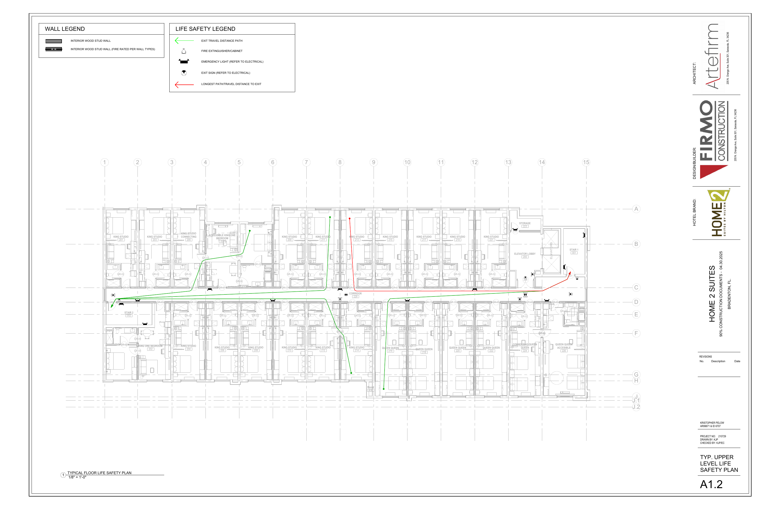
A1.2 · Upper-floor life safety Home2 Suites · Bradenton
SYMBOL TAKEOFF / COUNTS
22 numbered symbols · select a type to isolate its marks.
PLAN NOTES / ROOMS / ASSEMBLIES
01 · Interior wood-stud wall
Wall legend identifies an interior wood-stud wall. Match each wall to the A0.2 assembly for stud size, board layers, insulation and finish.
02 · Fire-rated wood-stud wall
Separate wall-legend symbol identifies fire-rated interior wood-stud construction, with rating per wall types. Link the selected assembly and opening/penetration details to corridor and enclosure locations.
03 · Standard king studios · 15
201, 203, 209, 211, 213, 215, 217, 219, 221; 204, 206, 208, 210, 212, 214.
04 · Connecting king studio · 1
205. Coordinate connecting-door assembly and hardware with the enlarged room plan and door schedule.
05 · King one-bedroom · 1
202, adjacent to the west stair.
06 · Accessible king one-bedroom · 1
207. Green travel path connects this room to the west exit stair. Coordinate its room layout and door approach with A0.3.
07 · Queen-queen rooms · 4
216, 218, 220 and 222, along the southeast wing.
08 · Connecting queen-queen · 1
224. Coordinate connecting-door assembly and hardware with the enlarged room plan and door schedule.
09 · Accessible queen-queen · 1
226 at the southeast end. Coordinate the accessible room route and door clearances with A0.3.
10 · Exit stairs · 2
Stair 2 / 002 is shown at the west end; Stair 1 / 001 at the east end. Corridor 228 connects the two stair approaches.
11 · Exit travel paths
Green lines show travel toward the stairs. The red longest-path route starts in King Studio 213 and proceeds east along Corridor 228 to Stair 1.
12 · Emergency lighting / exit signs
Life-safety legend refers emergency lighting and exit signs to electrical drawings. Match upper-floor locations and sign direction to the corresponding electrical floor sheet.
13 · Fire extinguisher / cabinet
Life-safety legend includes extinguisher/cabinet. Coordinate selected cabinet, mounting and wall recess with the wall assembly and accessible corridor clear width.
14 · Elevator lobby / storage
Elevator Lobby 200 and Storage 223 are at the northeast core. Coordinate elevator-lobby openings and storage door with the door schedule and enclosure details.
SOURCE
A1.2 · 04.30.2025 · PDF page 10
36″ × 24″ sheet
Select an item to highlight its source.
SHOWN PLAN COUNTS
BROKEN CHAINS & PLAN ISSUES
PI-01 · Coordination
Stair room numbers reverse between sheets: A1.1 labels west Stair 2 as 001 and east Stair 1 as 002; A1.2 labels west Stair 2 as 002 and east Stair 1 as 001. Reconcile schedules and stair references.
PI-02 · Coordination
A small space near the south edge is labeled “Room 436” on this 200-series plan. Confirm its room name, number and use.
BC-01 · Coordination
The red longest-path route from Room 213 has no printed length. Link its measured travel distance and the upper-floor egress criteria before closing the life-safety review.
BC-02 · Coordination
“Typical upper level” does not identify the applicable floors. Match this layout and the 24 shown guestrooms to each upper-floor plan before multiplying quantities.
BC-03 · Coordination
Link the fire-rated wood-stud legend to specific A0.2 wall types and rated door/penetration details at corridors, stairs and shafts.
BC-04 · Coordination
Match emergency lights and exit signs to each corresponding upper-floor electrical sheet, including exit direction and emergency supply.
BC-05 · Coordination
Coordinate accessible rooms 207 and 226 with enlarged room plans, door hardware and A0.3 clearances; carry each applicable floor’s room numbers.
BC-06 · Cabinet locations
A1.2 includes the fire extinguisher/cabinet symbol in its legend but plots no locations. Obtain the upper-floor cabinet/extinguisher layout and coordinate wall recesses and corridor clearance.
Add working issue
Working notes · This session