A0.3 · ADA information Home2 Suites · Bradenton
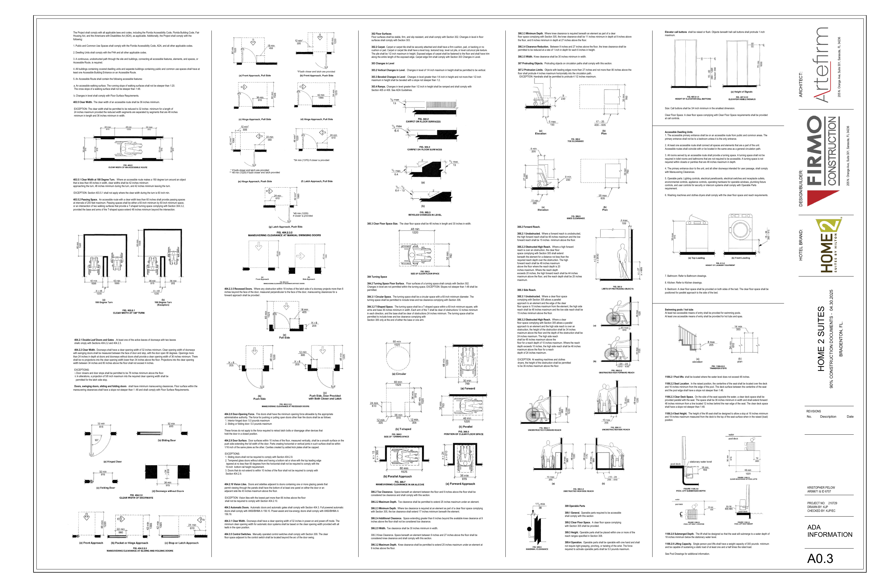
DETAIL / SCOPE REGISTER
01 · Accessible route
Connect accessible site/building features with a continuous unobstructed route and accessible entrance. Walking-surface running slope: 1:20 maximum; cross slope: 1:48 maximum. Clear width: 36″ minimum. A 32″ restriction is permitted for 24″ maximum length, separated by segments at least 48″ long and 36″ wide.
02 · Turns / passing spaces
For a 180° turn around an object under 48″ wide: approach 42″ minimum, turn 48″ minimum, exit 42″ minimum; exception where the turn is 60″ minimum. Routes under 60″ wide need passing spaces at intervals of 200′ maximum: 60″ × 60″ or the specified T intersection with 48″ extensions.
03 · Door opening / approach
32″ minimum clear opening, measured at 90° for swinging doors. Openings over 24″ deep require 36″ clear. No projections below 34″; between 34″ and 80″, projection limit is 4″. Door closers/stops may be at 78″ minimum. At double-leaf doors, at least one active leaf must meet the cited clear-width and maneuvering requirements. Check each approach diagram.
04 · Door maneuvering
Apply the figure matching front, hinge-side or latch-side approach and push/pull direction; include closer and latch conditions. Maneuvering surface slope: 1:48 maximum. For recesses: an obstruction within 18″ of the latch side and projecting more than 8″ triggers forward-approach clearance. Sliding/folding-door approach figures are also shown.
05 · Door hardware / surfaces
Interior hinged and sliding/folding opening force: 5 lb maximum, excluding fire doors and latch release. Fire-door force follows the appropriate authority. Provide smooth push-side surface within 10″ of floor; joints within 1/16″ plane and capped kick-plate cavities. The sheet lists exceptions for sliding doors, certain tempered-glass doors, and doors ending more than 10″ above floor. Vision-lite bottom: 43″ maximum; exception when lowest glass is above 66″.
06 · Automatic doors
Full-powered doors: referenced ANSI/BHMA A156.10; power-assist/low-energy: A156.19. Clear opening 32″ in power-on and power-off modes with all leaves open. Control switches need compliant operable parts and clear floor space beyond the door-swing arc.
07 · Floor finishes / thresholds
Stable, firm, slip-resistant surfaces. Carpet securely attached; firm pad/backing or none; pile height 1/2″ maximum; exposed edges fastened and trimmed. Level change up to 1/4″ may be vertical. Over 1/4″ through 1/2″: bevel at 1:2 maximum. Over 1/2″: ramp under the sheet’s referenced Sections 405/406.
08 · Clear floor / turning space
Clear floor space: 30″ × 48″. Circular turning space: 60″ minimum diameter. T-turn fits a 60″ square with 36″ minimum arms/base, 12″ clear arm extensions and 24″ clear base extension; permitted knee/toe overlap is limited as described. Turning surfaces: no level changes; slopes up to 1:48. Alcove figures show additional approach clearances.
09 · Toe / knee clearance
Toe zone: floor to 9″ high; 30″ minimum width; depth 17″ minimum where required, 25″ maximum. Extension over 6″ beyond available knee clearance is excluded. Knee zone: 9″–27″ high; 30″ minimum width; at least 11″ deep at 9″ high and 8″ deep at 27″ high; 25″ maximum depth. Reduction rate: 1″ depth per 6″ height.
10 · Protruding objects
Objects with leading edges above 27″ and up to 80″ may project 4″ maximum into circulation paths. Handrail exception: 4-1/2″ maximum. Coordinate cabinets, signage, devices and fixtures along routes.
11 · Reach ranges
Unobstructed forward and side reach: 15″–48″. Forward obstruction: reach depth ≤20″ allows 48″ high; depth >20″ to 25″ allows 44″ high. Side obstruction: 34″ maximum height and 24″ maximum depth; reach ≤10″ allows 48″ high, >10″ through 24″ allows 46″ high. Laundry obstruction-height exception: 36″.
12 · Operable parts
Provide clear floor space and place operable parts within reach ranges. One-hand operation without tight grasping, pinching or wrist twisting; activation force 5 lb maximum. Apply to lighting, panels, switches, receptacles, environmental/appliance controls, windows, plumbing and security/intercom controls.
13 · Elevator call controls
Call buttons raised or flush, at least 3/4″ in the smallest dimension; objects beneath call buttons may project 1″ maximum. Provide clear floor space. Coordinate call-button and visible-signal mounting with the sheet’s elevator figures and elevator submittal.
14 · Accessible room layout
Accessible primary entrance on an accessible route; not through a bedroom unless it is the only entrance. Connect unit spaces/elements to circulation and provide turning spaces, subject to the printed bathroom and shallow-closet exceptions. Door maneuvering, controls and laundry must comply with the sheet requirements. Clear parallel approach on both sides of bed. Follow bathroom and kitchen drawings.
15 · Pool / spa access
A0.3 calls for at least two accessible means of pool entry and one for hot tubs/spas. Follow pool drawings for the selected access systems; transfer-step dimensions are illustrated on this sheet.
16 · Pool-lift assembly
Lift at water depth ≤48″. Raised seat centerline ≥16″ from pool edge; intervening deck slope ≤1:48. Clear deck space 36″ wide × 48″ forward from a line 12″ behind rear seat edge; slope ≤1:48. Raised seat height 16″–19″; submerged seat ≥18″ below water. Capacity ≥300 lb with static-load resistance ≥1.5× rated load.
SOURCE
A0.3 · 04.30.2025 · PDF page 8
36″ × 24″ sheet
Select a requirement to highlight its source.
KEY DIMENSIONS · A0.3
BROKEN CHAINS & PLAN ISSUES
BC-01 · Coordination
Link route widths, slopes, passing spaces and protrusion clearances to site, civil and floor-plan layouts.
BC-02 · Coordination
Match each door to its approach diagram, actual swing, latch/closer and schedule hardware. Carry opening-force and automatic-control requirements into submittals.
BC-03 · Coordination
Coordinate reach ranges and knee/toe spaces with millwork, appliances, plumbing fixtures and electrical-device locations.
BC-04 · Coordination
Link accessible bed clearances, turning spaces, laundry, bathrooms and kitchens to the applicable enlarged room plans.
BC-05 · Coordination
Coordinate elevator call controls and visible signals with elevator drawings and the equipment submittal.
BC-06 · Coordination
Reconcile the two pool-entry means stated on A0.3 with the pool details and selected lift/transfer systems; carry the lift capacity and deck-space requirements.
PI-01 · Coordination
The sheet uses dwelling-unit/FHA language within a hotel set. Confirm the project-specific accessible-room criteria and scope with the architect.
Add working issue
Working notes · This session