E6.1 · Electrical Panels Schedule Home2 Suites · Bradenton
TAKEOFF / ACTUAL PLAN COUNTS
Select a type to isolate its numbered source marks.
IMPORTANT HVAC / ELECTRICAL NOTES
QUANTITIES / DIMENSIONS
Select a row to show its exact source basis.
ASSEMBLIES / ACCESSORIES
L2.A
120/208V, 3PH, 4W; 250 AMP COPPER bus; 250 AMP M.L.O; 22 KA; fed from MDP; STORAGE 2ND FLOOR. 42 complete circuit rows.
L1.B
120/208V, 3PH, 4W; 100 AMP COPPER bus; 100 AMP M.L.O; 30 KA; fed from MDP; ELEC. RM. 1ST FLOOR. 42 complete circuit rows.
L2.B
120/208V, 3PH, 4W; 250 AMP COPPER bus; 250 AMP M.L.O; 22 KA; fed from MDP; STORAGE 2ND FLOOR. 42 complete circuit rows.
L1.C
120/208V, 3PH, 4W; 200 AMP COPPER bus; 200 AMP M.L.O; 42 KA; fed from MDP; ELEC. RM. 1ST FLOOR. 66 complete circuit rows.
L1.A
120/208V, 3PH, 4W; 225 AMP COPPER bus; 225 AMP M.L.O; 42 KA; fed from MDP; ELEC. RM. 1ST FLOOR. 42 complete circuit rows.
L1.D
120/208V, 3PH, 4W; 200 AMP COPPER bus; 200 AMP M.L.O; 42 KA; fed from MDP; ELEC. RM. 1ST FLOOR. 42 complete circuit rows.
NOTES / REFERENCES
1. CONTRACTOR SHALL PROVIDE A PERMANENTLY AFFIXED LABEL WITH THE MAXIMUM FAULT CURRENT PER ARTICLE 110.24. THE LABEL SHALL INCLUDE THE DATE THE FAULT-CURRENT CALCULATION WAS PERFORMED AND BE OF SUFFICIENT DURABILITY TO WITHSTAND THE ENVIRONMENT INVOLVED. THE LABEL SHALL BE 2”X3” IN SIZE AND SHALL BE BLUE LETTERING ON A CONTRASTING BACKGROUND.
2. CONTRACTOR TO VERIFY FINAL CURRENT VALUES FROM ELECTRICAL UTILITY COMPANY AND PROVIDE AIC PROTECTION ACCORDINGLY.
3. AIC RATINGS OF ALL THE PANELS & BRANCH BREAKERS SHALL MATCH THE FAULT CURRENT OF THE TRANSFORMER.
L1.B note 1. CONTROLLED BY A 20A. MECH. HELD LIGHTING CONTACTORS WHICH IS CONTROLLED BY A 7-DAY, N-1 TIME CLOCK WITH 4 HRS BATTERIES IN PANEL L1.B.
L1.B note 2. PROVIDE HANDLE TIES FOR CIRCUIT BREAKERS TO DISCONNECT ALL UNGROUNDED CONDUCTORS SIMULTANEOUSLY ON MULTI-WIRE BRANCH CIRCUITS.
L1.C note 1. CONTRACTOR MUST PROVIDE ISOLATED GROUNDS IN THE PANEL.
L1.D note 1. FIELD VERIFICATION BREAKER SIZES, BREAKER TYPE, ETC WITH LAUNDRY MANUFACTURER AND CODES REQUIREMENTS PRIOR TO INSTALLATION.
L1.D note 2. FIELD VERIFICATION HPs, BREAKER SIZES, CABLES SIZES FOR BOOSTER PUMPS WITH THE PLUMBING EQUIPMENT SCHEDULE PRIOR TO INSTALLATION.
SOURCE
E6.1 · Engineering PDF page 54
Issued 11.22.2024 · NTS / SCHEDULE · NO PLAN-SCALE LF
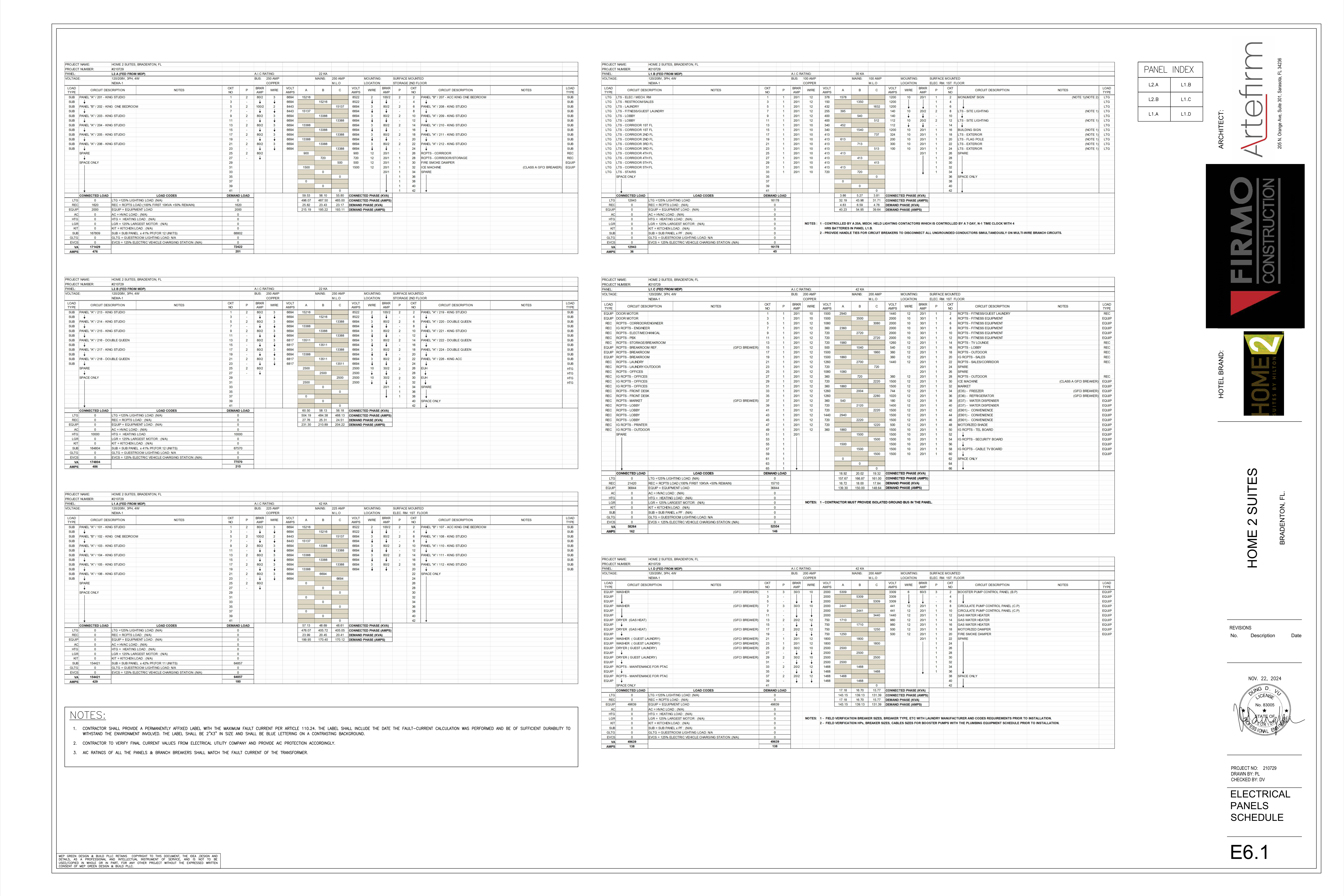
ELECTRICAL PANELS SCHEDULE
BROKEN CHAINS & PLAN ISSUES
1 · Arithmetic
L1.A printed guestroom row values sum to 154,422 VA, while the connected SUB and total VA rows print 154,421 VA: 1 VA difference.
2 · Arithmetic
L2.A printed guestroom row values sum to 167,810 VA, while the connected SUB row prints 167,809 VA; with REC 1,620 VA and EQUIP 2,000 VA, the component sum is 171,430 VA versus the printed total 171,429 VA: 1 VA difference.
3 · Description Load Mismatch
L2.B circuit 2 is labeled PANEL “A” / 219 - KING STUDIO but prints 8,522 VA on each pole, unlike the 6,694 VA used for other King Studio feeds; no correction was inferred.
4 · Description Load Mismatch
L2.B panels /220, /222, and /224 are labeled DOUBLE QUEEN but print 6,694 VA on each pole, while /216 and /218 DOUBLE QUEEN print 6,817 VA; no correction was inferred.
5 · Coordination
General Notes 2-3 require utility-current verification and coordination of panel/branch-breaker AIC ratings with transformer fault current.
6 · Coordination
L1.D laundry and booster-pump breaker/cable data are explicitly subject to field verification; scheduled values must not be treated as finally coordinated.
7 · Reference Chain
The plumbing equipment schedule needed for L1.D booster-pump verification is not identified by sheet number on E6.1.
8 · Reference Chain
Guestroom subpanel labels provide room numbers and types but not a cross-sheet branch-device reconciliation; downstream device quantities cannot be inferred from this schedule.
9 · Arithmetic
L1.B printed circuit/phase-pair values sum to 12,947 VA, while the connected LTG and total VA rows print 12,943 VA: 4 VA difference. The printed demand value of 16,178 VA is preserved without correction.
10 · Arithmetic
L1.D printed circuit/phase-pair values sum to 49,641 VA, while the connected EQUIP and total VA rows print 49,639 VA: 2 VA difference. Connected and demand totals are preserved as printed.
11 · Ev
EVCS appears only as zero/N/A load-code rows on all six schedules; no EV circuit is scheduled on E6.1.
12 · Critical Cross Sheet Conflict
L1.A is independently reported as printing 12 guest feeder rows 101-112, while E3.0 registers 11 guestrooms 101-108, 110, 112, and 114. E3.0 identifies 109 as Mechanical and 111 as Engineer; L1.A assigns a guest feeder to 111 and omits guestroom 114. L1.A's own SUB demand formula says FOR 11 UNITS. No correction or feeder reassignment is inferred.
Add working issue
Working notes · This session