E3.1 · Power Second Floor Plan Home2 Suites · Bradenton
TAKEOFF / ACTUAL PLAN COUNTS
Select a type to isolate its numbered source marks.
IMPORTANT HVAC / ELECTRICAL NOTES
QUANTITIES / DIMENSIONS
Select a row to show its exact source basis.
ASSEMBLIES / ACCESSORIES
Second-floor power
Eight receptacles, two EUH-2 power connections, two panelboards, four home-run markers and two keynote references are individually retained.
EUH-2 reconciliation
Two stair EUH connections reconcile to the two M2.1 EUH-2 units and M1.1 schedule data; no separately plotted disconnect/control accessory is added.
Guestroom scope
Twenty-four room labels are evidence only. E3.1 has no interior guestroom power symbols or typical-room reference.
NOTES / REFERENCES
1. FOR HOME RUNS (FROM UNITS) 100 FT OR MORE, THE ELECTRICAL CONTRACTOR HAS TO CHECK THE VOLTAGE DROP AND SELECT THE SUITABLE CABLES SIZE TO COMPLY WITH THE MAXIMUM ALLOWED VOLTAGE DROP FOR THE FEEDER CONDUCTOR (3%). THE MAXIMUM COMBINED VOLTAGE DROP ON BOTH INSTALLED FEEDER CONDUCTORS AND BRANCH CIRCUIT CONDUCTORS TO THE FARTHEST CONNECTED LOAD OR OUTLET SHALL NOT EXCEED 5 PERCENT.
2. THE CONTRACTOR SHALL VERIFY WITH THE OWNER/FRANCHISE FOR THE QUANTITIES AND LOCATIONS OF THE LOW VOLTAGE SYSTEM DEVICES (CAMERA, CARD READER, WIRELESS ACCESS POINT, ETC.) AND PROVIDE ALL NECESSARY ACCESSORIES TO COMPLETE THE WIRING, POWER SUPPLY FOR THE DEVICES AS PER THE MANUFACTURER SPECIFICATIONS/ INSTALLATION GUIDELINES.
3. THE CONTRACTOR SHALL VERIFY LOCATION OF ALL FLOOR OUTLETS WITH FURNITURE/ ARCH. PRIOR TO INSTALLATION.
4. ELECTRICAL CONTRACTORS MUST VERIFY ALL ELECTRICAL REQUIREMENTS WITH THE HVAC AND PLUMBING SYSTEMS TO PROVIDE ALL NECESSARY ACCESSORIES TO COMPLETE THE CONTROL WIRING FOR THE MOTORS.
1. CONTRACTOR SHALL PROVIDE J-BOXES FOR FIRE SMOKE DAMPERS AT 2ND FLOOR, CONNECT TO L2.A-30, USING 2#12, 1/2"C.
1. THE PANELBOARD SHALL BE LOCKABLE AND ACCESSIBLE TO QUALIFIED PERSONS ONLY. FIELD VERIFICATION OF THE BEST LOCATION OF ELECTRICAL PANELS PRIOR TO INSTALLATION. THE LOCATION OF ELECTRICAL PANELS MUST COMPLY WITH 110.26 AND 240.24 OF THE NEC.
Eight wall-mounted 20A duplex receptacle symbols are exactly plotted; seven are unqualified and one has the local callout HP.
Two EUH power connections and two panelboards are plotted.
Four home-run arrows carry L2.A-26, L2.A-28, L2.B-26,28 and L2.B-30,32.
Six visible circuit-path objects total 181.122 drawing LF, rounded to 181.0 LF at the printed scale only.
Twenty-four guestroom references contain zero E3.1 power-device symbols and no typical-room cross-reference is printed on this sheet.
The L2.A-30 fire/smoke-damper circuit is note-only; no J-box or damper occurrence is plotted.
SOURCE
E3.1 · Engineering PDF page 43
Issued 11.22.2024 · 1/8" = 1'-0" · PRINTED SCALE ONLY
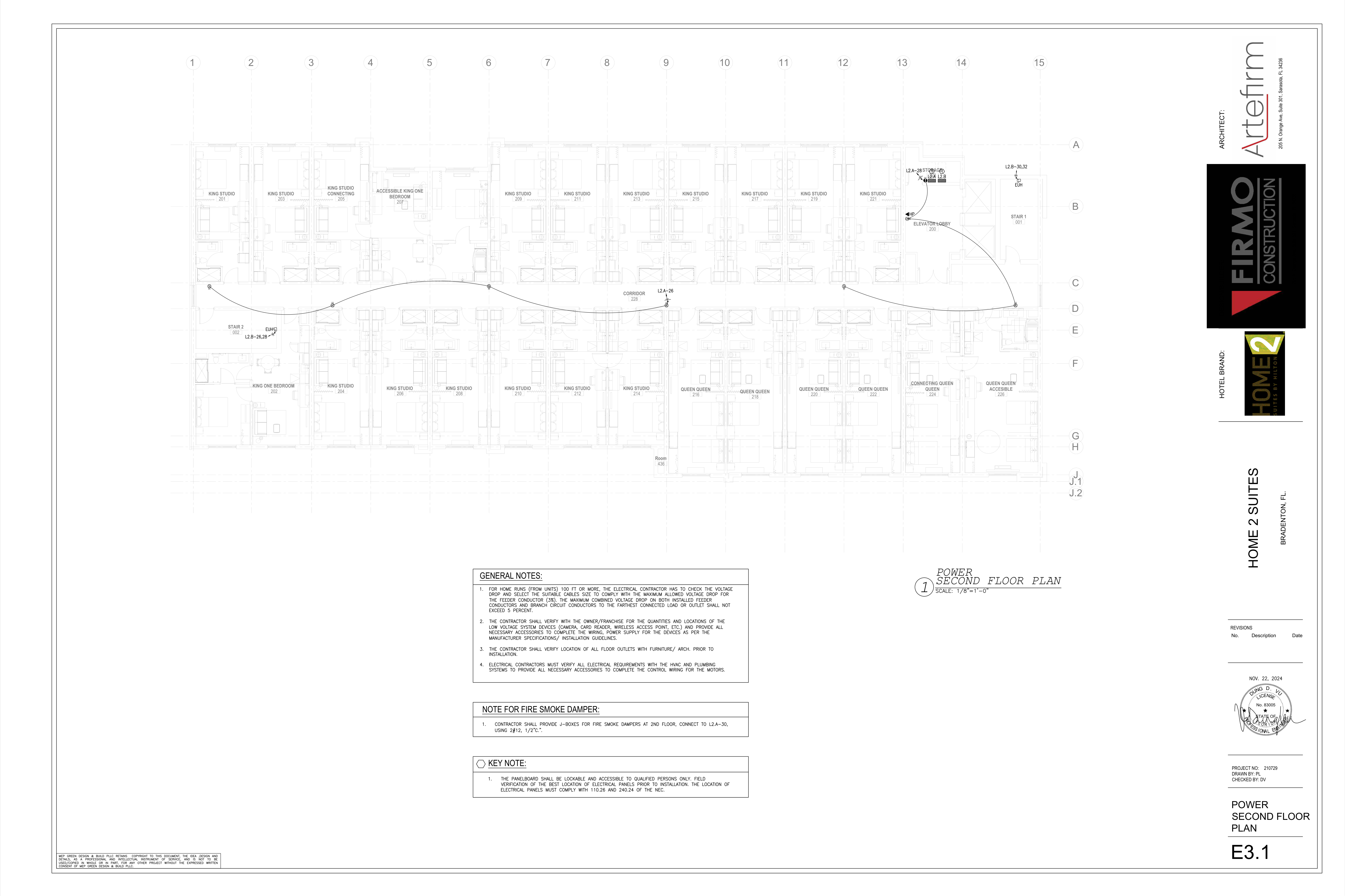
POWER SECOND FLOOR PLAN
BROKEN CHAINS & PLAN ISSUES
E31-01 · Measurement
The view title prints 1/8 inch = 1 foot, but no written dimension chain permits independent calibration. The 181.122 LF is provisional visible drawing-path length only.
E31-02 · Scope
All 24 guestrooms have architectural room labels but no power devices or E3.1 typical-room reference. Do not multiply a typical-room device set into installed quantities from this sheet.
E31-03 · Broken-Reference
The fire/smoke-damper note requires second-floor J-boxes on L2.A-30 using 2#12 in 1/2-inch conduit, but E3.1 plots no damper/J-box locations, quantity, mechanical sheet callout or detail reference.
E31-04 · Routing
The four home-run arrows identify circuits but omit complete routes to L2.A/L2.B, vertical segments, conduit paths and conductor allocation. Installed route, conduit and conductor LF remain null.
E31-05 · Source-Obscured
One Elevator Lobby duplex is called out HP. HP is not defined on E3.1 or the E1.1 symbol/abbreviation list, so its expansion and any special rating/accessory requirement are not guessed.
E31-06 · Equipment
Two EUH connections reconcile with staircase EUH-2 equipment, but no separate disconnect, controller or accessory is distinctly plotted on E3.1. General Note 4 requires coordination with HVAC/plumbing.
E31-07 · Panel-Coordination
L2.A and L2.B are shown with Keyed Note 1 field-location language. Their final field location is therefore not fixed solely by the plotted position.
E31-08 · Schedule-Chain
No panel schedule/detail reference is printed next to L2.A/L2.B or the circuit callouts on E3.1; breaker and conductor confirmation requires the panel schedule sheets.
E31-09 · Low-Voltage
General Note 2 names cameras, card readers and wireless access points, but none are plotted on E3.1 and final quantities/locations are explicitly delegated to owner/franchise verification.
E31-10 · Floor-Outlets
General Note 3 governs floor outlets, but no floor-outlet symbol is plotted on E3.1. The note does not establish a quantity.
E31-11 · Background-Conflict
A stray ROOM 436 label appears below this 200-series second-floor plan; it is treated as an architectural-background artifact.
E31-12 · Revision
The revision block is blank; no revision delta is available for reconciliation.
Add working issue
Working notes · This session