E3.2 · Power Third Floor Plan Home2 Suites · Bradenton
TAKEOFF / ACTUAL PLAN COUNTS
Select a type to isolate its numbered source marks.
IMPORTANT HVAC / ELECTRICAL NOTES
QUANTITIES / DIMENSIONS
Select a row to show its exact source basis.
ASSEMBLIES / ACCESSORIES
L3.A-34 west/central branch
Five outlet symbols including one keynote-2 above-ceiling outlet, one distinct C.P-tagged device symbol and one L3.A-34 callout; four visible path segments form the plotted branch.
L3.A-26 branch
One outlet symbol with L3.A-26 callout at the east end of the central branch.
L3.A-28 / HP / panels
Panels L3.A and L3.B, one L3.A-28 callout, an HP-tagged outlet and two additional outlet symbols; three visible path segments.
Guestroom scope
Twenty-four room labels are evidence only; no guestroom device multiplier is authorized by E3.2.
NOTES / REFERENCES
1. For home runs from units 100 ft or more, check voltage drop and select suitable cable size for maximum feeder-conductor drop of 3%; maximum combined voltage drop on installed feeder and branch-circuit conductors to farthest connected load/outlet shall not exceed 5%.
2. Verify with owner/franchise quantities and locations of low-voltage devices (camera, card reader, wireless access point, etc.) and provide accessories, wiring and power supply per manufacturer specifications/installation guidelines.
3. Verify locations of all floor outlets with furniture/architect prior to installation.
4. Verify all electrical requirements with HVAC and plumbing systems and provide accessories necessary to complete motor control wiring.
1. Contractor shall provide J-boxes for fire smoke dampers at 3rd floor, connect to L3.A-30 using 2#12, 1/2-inch conduit.
1. Panelboard shall be lockable and accessible to qualified persons only. Field-verify best panel location before installation. Panel locations must comply with NEC 110.26 and 240.24.
2. Receptacle outlets above the ceiling for maintenance.
{"fact": "Installed/device plotted symbols", "formula": "8 outlet symbols + 1 C.P-tagged device + 2 panels", "value": 11}
{"fact": "Circuit callouts", "tags": ["L3.A-34", "L3.A-26", "L3.A-28"], "value": 3}
{"drawnPathLF": 182.1792, "fact": "Visible drawn paths", "quantityStatus": "diagram path only; not installed routing", "roundedHalfFootRunSum": 182.5, "value": 7}
{"fact": "Guestrooms shown", "quantityStatus": "room evidence only; no power-device takeoff inferred", "value": 24}
SOURCE
E3.2 · Engineering PDF page 44
Issued 11.22.2024 · 1/8" = 1'-0" · PRINTED SCALE ONLY
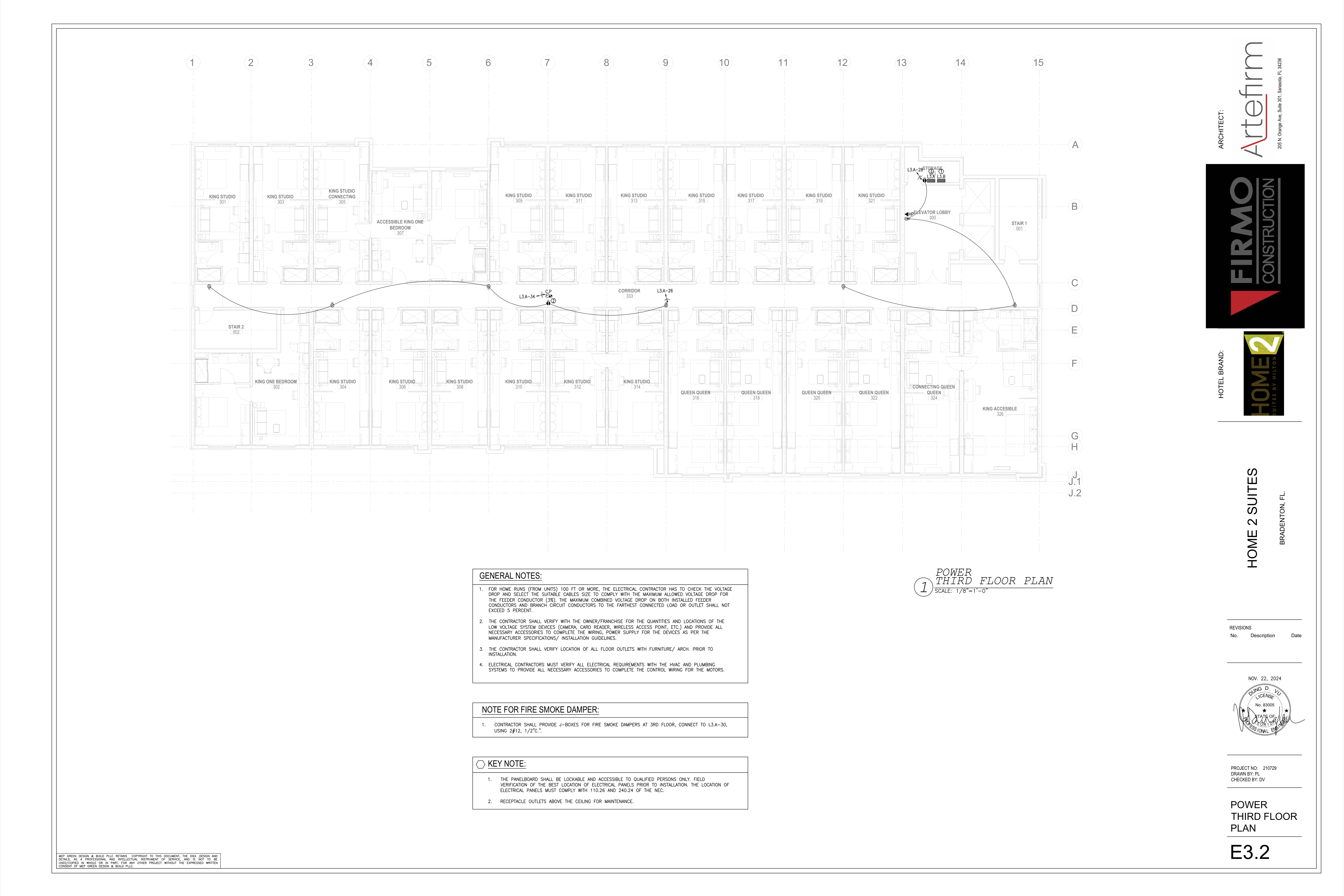
POWER THIRD FLOOR PLAN
BROKEN CHAINS & PLAN ISSUES
E32-01 · High
No guestroom receptacles, controls or equipment connections are plotted and no explicit typical-room mapping is present on E3.2; 24 guestroom labels cannot support installed device quantities.
E32-02 · High
Fire Smoke Damper Note requires third-floor J-boxes on L3.A-30 with 2#12 in 1/2-inch conduit, but no damper/J-box symbols, locations or quantity mapping are plotted on this sheet. Quantity and path are non-certifiable.
E32-03 · High
Visible curves are schematic plan connections only. Installed routing, verticals, hidden runs, fittings, slack and conductor/conduit LF are not shown and were not inferred.
E32-04 · High
Printed scale is legible but has no independent plan dimension calibration; path LF remains accepted=false.
E32-05 · Medium
C.P and HP abbreviations are not defined on E3.2. C.P is counted as a distinct plotted device symbol; HP is retained as the exact tag on one outlet and is not double-counted as another device.
E32-06 · Medium
Panel L3.A and L3.B locations are explicitly field-verification items under Key Note 1.
E32-07 · Medium
Circuit assignments L3.A-34, L3.A-26 and L3.A-28 are visibly separate callouts, but conductor counts/sizes are not printed for these plan paths. The 2#12/1/2-inch requirement belongs only to the unplotted L3.A-30 fire-smoke-damper note.
E32-08 · Medium
Key Note 2 identifies an above-ceiling maintenance receptacle at the C.P assembly; device mounting/serving-equipment identity is not further defined on this sheet.
Add working issue
Working notes · This session