E2.2 · Lighting Third Floor Plan Home2 Suites · Bradenton
TAKEOFF / ACTUAL PLAN COUNTS
Select a type to isolate its numbered source marks.
IMPORTANT HVAC / ELECTRICAL NOTES
QUANTITIES / DIMENSIONS
Select a row to show its exact source basis.
ASSEMBLIES / ACCESSORIES
Main corridor lighting/control network
25 PA-204, 22 R11, 7 EM, 6 corridor/east-core occupancy sensors, X/exit fixtures at core interfaces and one L1.B-21,23 home run are connected by visible arcs; curves are measured individually.
Stair 1 emergency assembly
2 S02, 2 EM, 1 X1, 2 X3 and 1 PA-204 visible in/at stair/core; keynote 1 references occur at S02/EM symbols.
Stair 2 emergency assembly
2 S02, 2 unconnected EM plus corridor-interface EM, 1 X1 and 1 X3 visible; keynote 1 references occur at S02/EM symbols.
Storage 323 assembly
1 S01, 1 EM, 1 unlabeled control symbol and EF-1, connected to an elevator-lobby R11 branch.
NOTES / REFERENCES
1. For home runs (from units) 100 ft or more, contractor must check voltage drop and select suitable cable size to comply with maximum allowed branch-circuit voltage drop (3%).
2. Verify owner-approved brands/models of low-voltage devices (camera, card reader, wireless access point, etc.) and provide accessories, wiring and power supply per manufacturer specifications/installation guidelines.
3. Exterior lighting requires automatic daylight/time/photo controls; dusk-to-dawn lighting by astronomical time switch or photosensor; time setting retained during power loss for at least 10 hours.
4. Occupancy-sensor switches turn lighting on instantaneously when occupied and off within 30 minutes after all occupants leave.
5. Emergency and exit lights on local normal-lighting circuits connect ahead of local switches; comply with NEC 700.12(F).
6. Emergency lighting: at least 10 foot-candles on stairs and 1 foot-candle on other walking surfaces per NFPA 101 Sections 7.8.1.3 and 7.9.
7. Low-level exit signs required in Group R-1 guestroom-serving areas per Sections 1013.1 and 1013.5; bottom 10–18 inches above floor; flush to door/wall; wall edge within 4 inches of latch-side door frame.
8. Verify mounting height for all wall-mounted fixture types with owner/architect before installation.
9. See typical guestroom plan for detailed room layout on sheets E4.0 and E4.1.
10. Wet/damp-location luminaires must prevent water entry/accumulation in wiring compartments, lamp holders or electrical parts and be suitable for the location.
11. Contractor shall verify and furnish exit signs complying with Section 1013 IBC.
12. Electrical contractor shall coordinate light fixtures and sprinkler heads with sprinkler contractor to comply with NFPA 13.
13. Sufficient emergency lighting levels will be determined during onsite inspection; additional emergency lighting may be required by field inspector.
1. Connect all type S02, X1 and X2 lights at staircase to L1.B-33 using 2#10, 1/2-inch conduit. Provide lock-on feature as required by NEC 700.12(I)(2)(3).
2. Corridor occupant-sensor controls shall uniformly reduce lighting power to an unoccupied setpoint not more than 50 percent of full power within 20 minutes after occupants leave (C405.2.1.4). Verify detection range, location and quantities with supplier/manufacturer before installation.
3. Fan will run continuously as noted on exhaust fan schedules (M1.1).
Plotted fixture subtotal: 74 (25 PA-204 + 22 R11 + 12 EM + 1 S01 + 4 S02 + 3 X1 + 2 X2 + 5 X3)
Controls: 8 (7 occupancy sensors + 1 unlabeled storage control symbol)
Fans: 2 (EF-1 + EF-1.1)
Guestrooms shown: 24
Visible drawn connection curves: 68
SOURCE
E2.2 · Engineering PDF page 39
Issued 11.22.2024 · 1/8" = 1'-0" · PRINTED SCALE ONLY
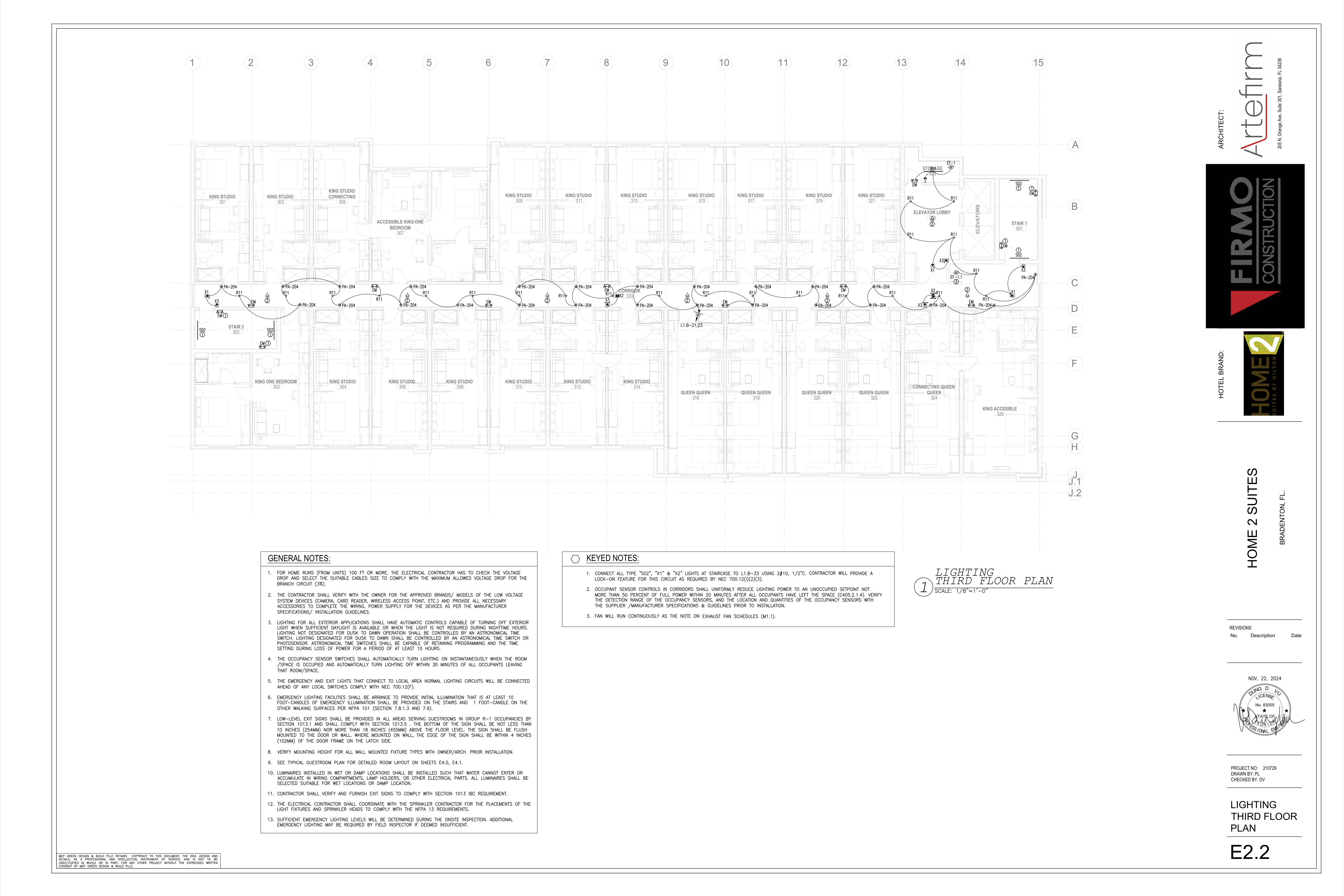
LIGHTING THIRD FLOOR PLAN
BROKEN CHAINS & PLAN ISSUES
E22-01 · High
Printed scale is legible, but no independent dimension string on E2.2 permits field-calibration. All curve LF is accepted=false and must not be treated as bid-ready installed routing.
E22-02 · High
General Note 9 sends detailed guestroom lighting to E4.0/E4.1. The 24 guestrooms on this plan contribute zero certifiable guestroom fixture/device quantities from E2.2 itself.
E22-03 · High
One home run is labeled L1.B-21,23, but individual branch-to-circuit allocation and conductor count are not shown. No conductor LF is certified.
E22-04 · Medium
Keyed Note 1 names S02, X1 and X2 for stair circuit L1.B-33, but five X3 occurrences are plotted at stair/core interfaces and X3 is not named in that note; scope requires clarification.
E22-05 · Medium
Keyed Note 3 cross-references exhaust-fan schedule M1.1 and is attached to EF-1.1; EF-1 in Storage 323 has no keynote-3 bubble on this sheet. Cross-sheet fan control/schedule scope remains unresolved here.
E22-06 · Medium
Keyed Note 2 explicitly requires supplier/manufacturer verification of occupancy-sensor range, location and quantities; seven plotted sensor occurrences are plan evidence, not a final approved control layout.
E22-07 · Medium
The storage control symbol connected to S01/EM/EF-1 has no legible local tag. It is counted once as an unlabeled control and not assigned a model/type.
E22-08 · Low
Fixture schedules/legend definitions for PA-204, R11, EM, S01/S02 and X1/X2/X3 are not on E2.2; counts certify plotted tags only, not manufacturer/model/specification.
E22-09 · High
Visible arcs express drawing connectivity. Concealed routing, drops, slack, junction boxes, grounds and conductor multiplication are not plotted and were not inferred.
Add working issue
Working notes · This session