E2.1 · Lighting Second Floor Plan Home2 Suites · Bradenton
TAKEOFF / ACTUAL PLAN COUNTS
Select a type to isolate its numbered source marks.
IMPORTANT HVAC / ELECTRICAL NOTES
QUANTITIES / DIMENSIONS
Select a row to show its exact source basis.
ASSEMBLIES / ACCESSORIES
Stair 1 001
Keyed Note 1 references S02, X1 and X2 at staircase on L1.B-33 using 2#10 in 1/2-inch conduit with lock-on feature.
Stair 2 002
Keyed Note 1; same qualification as Stair 1.
Storage 223
Visible control path links S01/control node/EF-1; exact control-device legend type is not printed on E2.1.
Guest corridor / Elevator Lobby 200
Keyed Note 2 controls apply; visible counts do not override supplier/manufacturer verification requirement.
EF-1.1 continuous fan
Keyed Note 3 references exhaust fan schedule M1.1; no circuit number is printed at the fan.
NOTES / REFERENCES
1. FOR HOME RUNS (FROM UNITS) 100 FT OR MORE, THE ELECTRICAL CONTRACTOR HAS TO CHECK THE VOLTAGE DROP AND SELECT THE SUITABLE CABLES SIZE TO COMPLY WITH THE MAXIMUM ALLOWED VOLTAGE DROP FOR THE BRANCH CIRCUIT (3%).
2. THE CONTRACTOR SHALL VERIFY WITH THE OWNER FOR THE APPROVED BRANDS/ MODELS OF THE LOW VOLTAGE SYSTEM DEVICES (CAMERA, CARD READER, WIRELESS ACCESS POINT, ETC.) AND PROVIDE ALL NECESSARY ACCESSORIES TO COMPLETE THE WIRING, POWER SUPPLY FOR THE DEVICES AS PER THE MANUFACTURER SPECIFICATIONS/ INSTALLATION GUIDELINES.
3. LIGHTING FOR ALL EXTERIOR APPLICATIONS SHALL HAVE AUTOMATIC CONTROLS CAPABLE OF TURNING OFF EXTERIOR LIGHT WHEN SUFFICIENT DAYLIGHT IS AVAILABLE OR WHEN THE LIGHT IS NOT REQUIRED DURING NIGHTTIME HOURS. LIGHTING NOT DESIGNATED FOR DUSK TO DAWN OPERATION SHALL BE CONTROLLED BY AN ASTRONOMICAL TIME SWITCH. LIGHTING DESIGNATED FOR DUSK TO DAWN SHALL BE CONTROLLED BY AN ASTRONOMICAL TIME SWITCH OR PHOTOSENSOR. ASTRONOMICAL TIME SWITCHES SHALL BE CAPABLE OF RETAINING PROGRAMMING AND THE TIME SETTING DURING LOSS OF POWER FOR A PERIOD OF AT LEAST 10 HOURS.
4. THE OCCUPANCY SENSOR SWITCHES SHALL AUTOMATICALLY TURN LIGHTING ON INSTANTANEOUSLY WHEN THE ROOM /SPACE IS OCCUPIED AND AUTOMATICALLY TURN LIGHTING OFF WITHIN 30 MINUTES OF ALL OCCUPANTS LEAVING THAT ROOM/SPACE.
5. THE EMERGENCY AND EXIT LIGHTS THAT CONNECT TO LOCAL AREA NORMAL LIGHTING CIRCUITS WILL BE CONNECTED AHEAD OF ANY LOCAL SWITCHES COMPLY WITH NEC 700.12(F).
6. EMERGENCY LIGHTING FACILITIES SHALL BE ARRANGE TO PROVIDE INITIAL ILLUMINATION THAT IS AT LEAST 10 FOOT-CANDLES OF EMERGENCY ILLUMINATION SHALL BE PROVIDED ON THE STAIRS AND 1 FOOT-CANDLE ON THE OTHER WALKING SURFACES PER NFPA 101 (SECTION 7.8.1.3 AND 7.9).
7. LOW-LEVEL EXIT SIGNS SHALL BE PROVIDED IN ALL AREAS SERVING GUESTROOMS IN GROUP R-1 OCCUPANCIES BY SECTION 1013.1 AND SHALL COMPLY WITH SECTION 1013.5. THE BOTTOM OF THE SIGN SHALL BE NOT LESS THAN 10 INCHES (254MM) NOR MORE THAN 18 INCHES (455MM) ABOVE THE FLOOR LEVEL. THE SIGN SHALL BE FLUSH MOUNTED TO THE DOOR OR WALL. WHERE MOUNTED ON WALL, THE EDGE OF THE SIGN SHALL BE WITHIN 4 INCHES (102MM) OF THE DOOR FRAME ON THE LATCH SIDE.
8. VERIFY MOUNTING HEIGHT FOR ALL WALL MOUNTED FIXTURE TYPES WITH OWNER/ARCH. PRIOR INSTALLATION.
9. SEE TYPICAL GUESTROOM PLAN FOR DETAILED ROOM LAYOUT ON SHEETS E4.0, E4.1.
10. LUMINAIRES INSTALLED IN WET OR DAMP LOCATIONS SHALL BE INSTALLED SUCH THAT WATER CANNOT ENTER OR ACCUMULATE IN WIRING COMPARTMENTS, LAMP HOLDERS, OR OTHER ELECTRICAL PARTS. ALL LUMINAIRES SHALL BE SELECTED SUITABLE FOR WET LOCATIONS OR DAMP LOCATION.
11. CONTRACTOR SHALL VERIFY AND FURNISH EXIT SIGNS TO COMPLY WITH SECTION 1013 IBC REQUIREMENT.
12. THE ELECTRICAL CONTRACTOR SHALL COORDINATE WITH THE SPRINKLER CONTRACTOR FOR THE PLACEMENTS OF THE LIGHT FIXTURES AND SPRINKLER HEADS TO COMPLY WITH THE NFPA 13 REQUIREMENTS.
13. SUFFICIENT EMERGENCY LIGHTING LEVELS WILL BE DETERMINED DURING THE ONSITE INSPECTION. ADDITIONAL EMERGENCY LIGHTING MAY BE REQUIRED BY FIELD INSPECTOR IF DEEMED INSUFFICIENT.
1. CONNECT ALL TYPE "S02", "X1" & "X2" LIGHTS AT STAIRCASE TO L1.B-33 USING 2#10, 1/2"C. CONTRACTOR WILL PROVIDE A LOCK-ON FEATURE FOR THIS CIRCUIT AS REQUIRED BY NEC 700.12(1)(2)(3).
2. OCCUPANT SENSOR CONTROLS IN CORRIDORS SHALL UNIFORMLY REDUCE LIGHTING POWER TO AN UNOCCUPIED SETPOINT NOT MORE THAN 50 PERCENT OF FULL POWER WITHIN 20 MINUTES AFTER ALL OCCUPANTS HAVE LEFT THE SPACE (C405.2.1.4). VERIFY THE DETECTION RANGE OF THE OCCUPANCY SENSORS, AND THE LOCATION AND QUANTITIES OF THE OCCUPANCY SENSORS WITH THE SUPPLIER /MANUFACTURER SPECIFICATIONS & GUIDELINES PRIOR TO INSTALLATION.
3. FAN WILL RUN CONTINUOUSLY AS THE NOTE ON EXHAUST FAN SCHEDULES (M1.1).
E2.1 contains 74 distinct plotted lighting/exit/emergency fixture occurrences: 25 PA-204, 22 R11, 12 EM, 1 S01, 4 S02, 3 X1, 2 X2 and 5 X3.
Seven occupant-sensor symbols, two exhaust-fan motor symbols, one unlabeled Storage 223 control node and one L1.B-17,19 home-run arrow are separately registered.
Twenty-four guestrooms are named on the plan, but no interior guestroom lighting symbols are plotted on E2.1; General Note 9 delegates detailed room layout to E4.0/E4.1.
Sixty-seven visible drawn connection splines total 409.435 drawing LF (409.5 LF rounded to the nearest 0.5 LF) at printed scale only.
No complete installed routing, vertical drops or conductor allocation can be certified from E2.1.
SOURCE
E2.1 · Engineering PDF page 38
Issued 11.22.2024 · 1/8" = 1'-0" · PRINTED SCALE ONLY
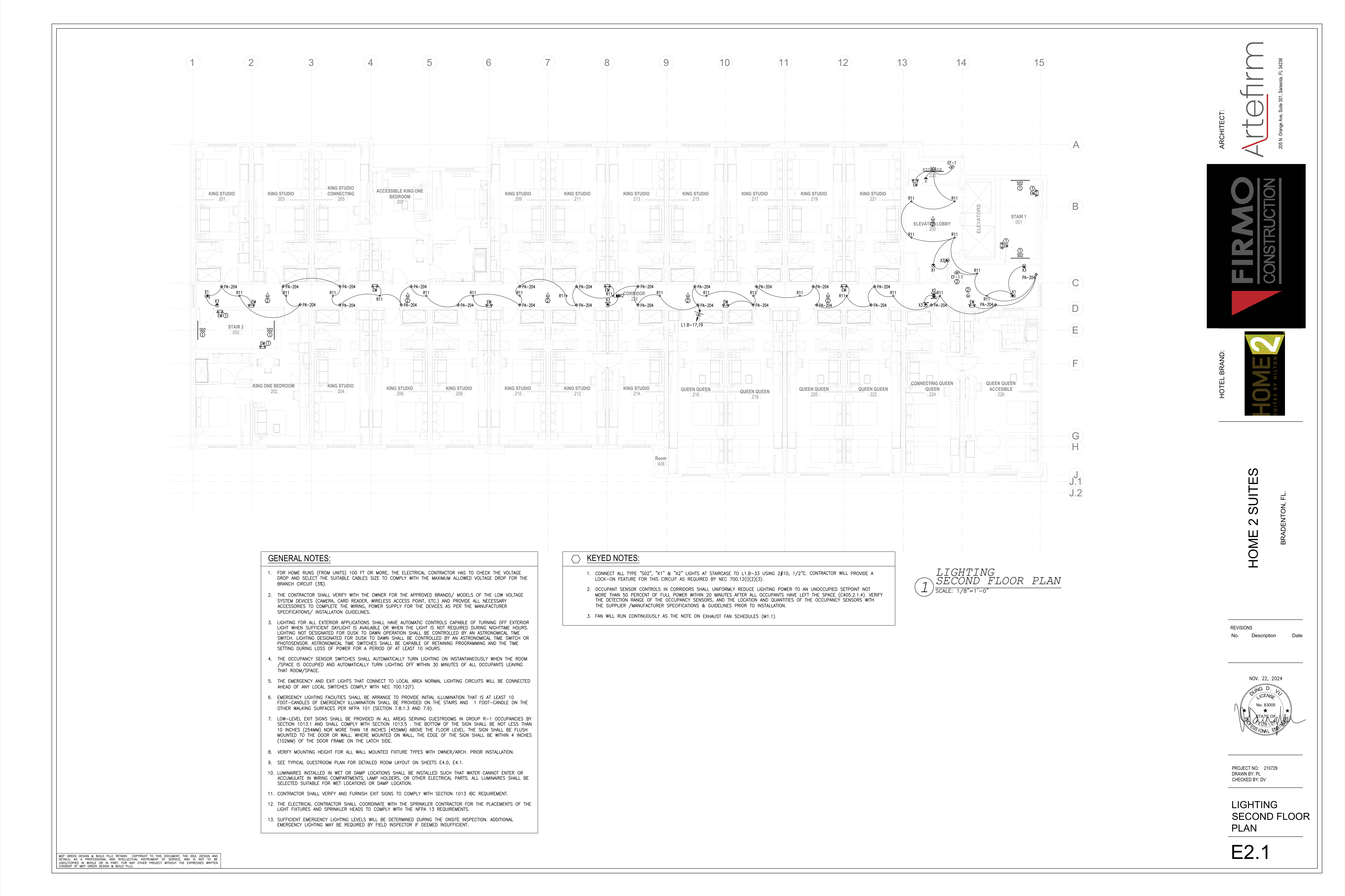
LIGHTING SECOND FLOOR PLAN
BROKEN CHAINS & PLAN ISSUES
E21-01 · Measurement
The view title prints 1/8 inch = 1 foot, but E2.1 contains no written dimension chain for an independent check. All 409.435 LF is provisional drawn-path length, not certified installed LF.
E21-02 · Scope
Guestroom interior lighting is intentionally absent. General Note 9 points to E4.0/E4.1; the 24 room references must not be multiplied into installed fixture quantities without auditing those typical plans and room-type mapping.
E21-03 · Coordination
Keyed Note 1 specifies staircase types S02, X1 and X2 on L1.B-33, while visible Stair 2 exit tags are X1 and X3 and the visible east-core/stair condition likewise includes X3. Confirm whether X3 is intended on the emergency circuit or the keyed note/tag is wrong.
E21-04 · Routing
The lone home-run arrow is labeled L1.B-17,19. It identifies two circuits but does not show their route to panel, wire count, individual switched legs, neutral/ground allocation or vertical path.
E21-05 · Control
Keyed Note 2 explicitly requires supplier/manufacturer verification of sensor detection range, final locations and quantities. Seven sensors are exactly plotted, but final installed sensor count is not design-certified by the note.
E21-06 · Equipment
EF-1.1 is directed to run continuously by M1.1, but no circuit number or complete power route is printed at either EF-1 or EF-1.1 on this sheet.
E21-07 · Source-Obscured
The filled control/switch symbol in Storage 223 is distinct and connected, but its device tag/type is not legible or printed locally. It is counted once without assigning a guessed device subtype.
E21-08 · Life-Safety
General Note 7 requires low-level exit signs in Group R-1 guestroom-serving areas, but E2.1 does not uniquely tag or differentiate low-level exit-sign occurrences from X1/X2/X3. Quantity is non-certifiable from this sheet.
E21-09 · Life-Safety
General Note 13 allows the field inspector to require additional emergency lighting. The 12 visible EM units and integral S02 emergency features are exact plotted counts, not guaranteed final installed counts.
E21-10 · Background-Conflict
A stray ROOM 436 label appears below the plan near grid 9 despite this being the second-floor 200-series plan. It is treated as an architectural-background artifact, not a room count.
E21-11 · Not-Shown
No distinct manual wall switch or dimmer tag is legibly plotted for the corridor network; do not infer switch quantities from the connection splines or occupancy-control notes.
E21-12 · Revision
The revision block is blank; no revision delta can be reconciled from this sheet.
Add working issue
Working notes · This session