A3.2 · Second Floor Reflected Ceiling Plan Home2 Suites · Bradenton
TAKEOFF / SOURCE COUNTS
Select a row for its source and quantity basis.
AREAS / LENGTHS
Select a quantity to show its source boundary.
ASSEMBLIES / RECONCILIATION
Source quantities
REF entries are references, REQ entries are requirements, SHOWN entries need final identification, and LOC entries count plotted callouts. These are not one installed-asset total.
Ceiling assemblies
Separate gypsum, acoustic tile, decorative fields, open zones and reference footprints. Resolve net deductions, local heights, edge profiles and supports before material ordering.
Furniture / equipment
Reconcile each object across plans, enlarged views, schedules and vendor packages. Optional, future, operator-furnished and alternative scope remain distinct.
Utilities / supports
Coordinate power, water, drainage, equipment clearances, mounting/backing and millwork partitions with selected equipment and trade drawings.
PLAN NOTES / REFERENCES
Printed1/8 inch =1 foot; normalized scale6.6667 pixels/foot. Shared grid6–7 and14–15 checked against dimensioned A2.16; no use of previous enlarged-room20px/ft scale.
Original CAD arcs/overdraws deduplicated at same centers. Height-tag circles and legend examples excluded from equipment totals. Symbol diameters are drawing geometry, not specified device sizes.
Main guestroom tags show8 feet where printed; service-band heights are often untagged and require enlarged-room/MEP coordination.
Finished ceiling fields, open-ceiling reference areas, unconfirmed shaft/stair areas and step-face allowances must not be summed as one material order.
Full original source text, room names, dimensions, height labels and vector evidence preserved.
A3.2/A3.3 finish legend says painted GB8-foot10-inch UNO; explicit8-foot room tags and7-foot6-inch elevator lobby tag override that general note where shown.
Floor-specific room identities retained; stairs/elevator shafts/storage with no ceiling height are reference geometry only.
SOURCE
A3.2 · PDF page33 · 36″ × 24″
Printed04.30.2025
Select a source region.
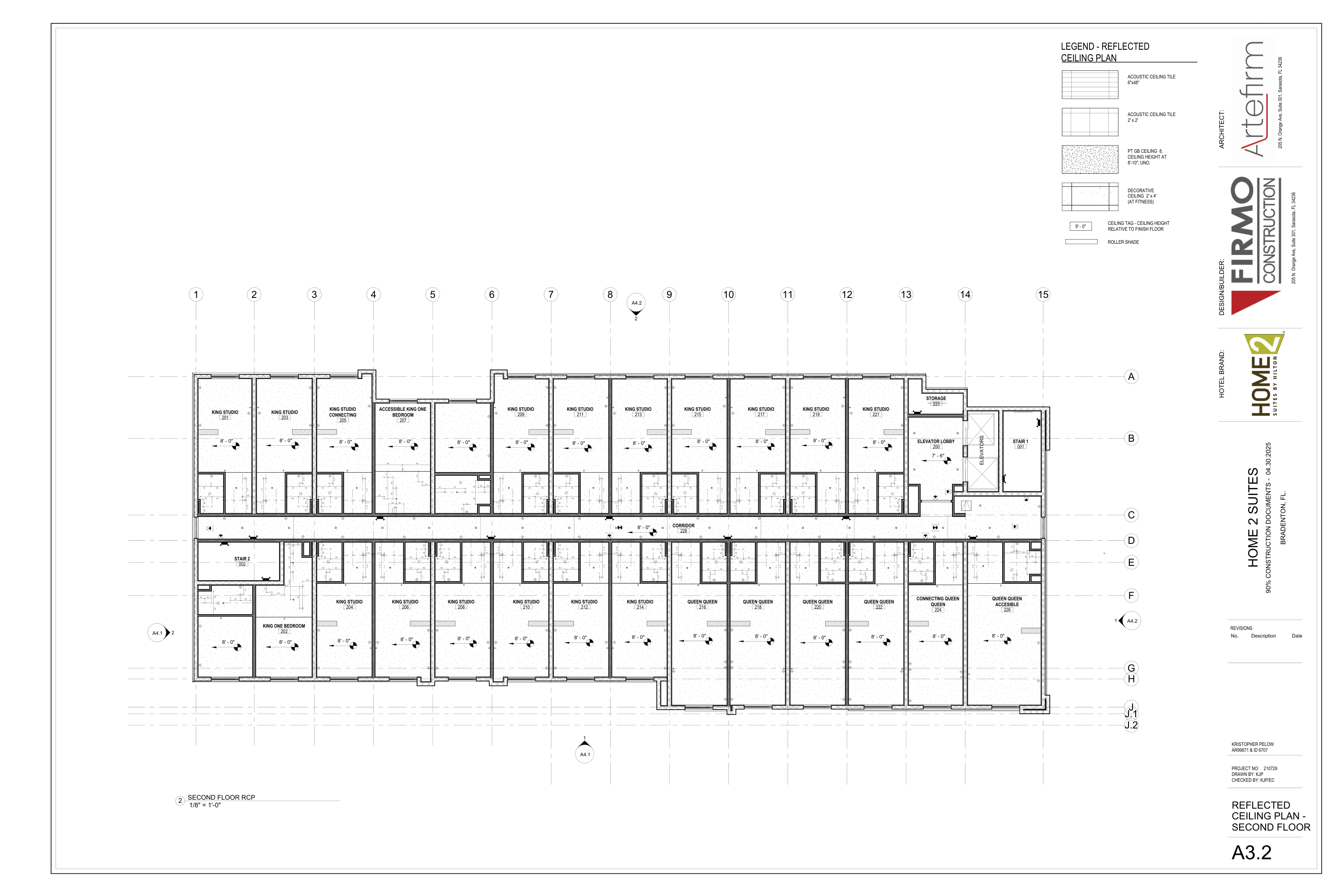
SECOND FLOOR REFLECTED CEILING PLAN
BROKEN CHAINS & PLAN ISSUES
BC-01 · Actual floor vs room-detail duplication
These are actual floor occurrences. Enlarged guestroom and lobby details describe the same assets; reconcile using room IDs before transferring quantities. Do not add typical-room device counts to RCP counts.
BC-02 · Device classifications and MEP coverage
Round sizes, square bath devices and directional rectangles are source geometries, not approved fixture products. Confirm fixtures, outlets, detectors, diffusers, sprinkler types and circuit/zone requirements with trade drawings. Unkeyed device classes remain SHOWN.
BC-03 · Service-band net area / lower ceilings
Combined entry/bath bands are gross horizontal references before internal partition/boxed-void deductions. This RCP often omits local service heights; do not silently apply main-room8 feet or a typical7-foot3-inch value.
BC-04 · Gypsum / tile / ceiling assemblies
Separate painted gypsum,2x2 tile,6x48 acoustic and2x4 decorative assemblies. Tile modules do not yield whole-panel ordering without edge layout, waste and support design. Resolve backing, fire/acoustic construction, finishes and soffit sections.
BC-05 · Scale and registration limits
Printed1/8 scale and shared building-grid registration support geometry. These RCPs have few overall dimension strings. Approximate traces and inherited clear-room references require final dimension confirmation before fabrication.
BC-06 · Wall-mounted / furniture light reconciliation
Guestroom ceiling backgrounds contain wall/furniture light symbols. Some room legends still retain deleted GR-208 references. Geometry count is not approval of every background lamp or an extra FF&E order.
SYNC · Mason Brain / estimate transfer
No verified Mason Brain synchronization or estimate import is claimed. Preserve actual floor, room, source geometry and unresolved classification when transferring.
PI-01 · Legend default vs explicit heights
Painted-GB legend default8 feet10 inches differs from explicit8-foot main rooms/corridor and7-foot6-inch elevator lobby. Apply local tags where present; untagged areas remain unresolved.
PI-02 · Untyped storage / stair / shaft ceilings
No finished-ceiling or height assumption assigned to storage, stair or elevator shaft reference footprints. Confirm exposed construction and any actual landings/soffits.
REF-01 · Elevation reference destinations
A3.2 points to A4.1 and A4.2 elevation/detail references. Retain the destination identities and verify exact numbered details during those sheets; not automatically resolved by a similar sheet name.
Add working issue
Working notes · This session